Galvanized malleable iron fittings are commonly used in various piping systems for their corrosion resistance and durability. These fittings can be compatible with a range of other fittings and piping materials, depending on the specific application and requirements.
Here are some types of fittings that are often compatible with galvanized malleable iron fittings:
Black Malleable Iron Fittings: Galvanized and black malleable iron fittings are typically compatible with each other, allowing for easy integration within the same piping system. Both types of fittings are made from malleable iron and can be threaded to create secure connections.
Galvanized Steel Fittings: Galvanized malleable iron fittings are also compatible with galvanized steel fittings. Both materials offer corrosion resistance and are commonly used together in plumbing, water distribution, and other piping applications.
Threaded Brass Fittings: Brass fittings with threaded connections are often compatible with galvanized malleable iron fittings. Brass is a durable and corrosion-resistant material that can be used in conjunction with galvanized malleable iron fittings in various plumbing and industrial applications.
Threaded PVC Fittings: PVC (polyvinyl chloride) fittings with threaded connections can be compatible with galvanized malleable iron fittings, especially in applications where corrosion resistance and non-metallic materials are preferred. PVC fittings are commonly used in water supply, irrigation, and drainage systems.
Stainless Steel Fittings: In some cases, stainless steel fittings with threaded connections may be compatible with galvanized malleable iron fittings. Stainless steel offers excellent corrosion resistance and strength, making it suitable for use in corrosive environments or applications requiring high durability.
Copper Fittings: Copper fittings with threaded connections can also be compatible with galvanized malleable iron fittings. Copper is often used in plumbing systems for its corrosion resistance and thermal conductivity, and it can be combined with galvanized malleable iron fittings in various applications.
Bronze Fittings: Bronze fittings with threaded connections may be compatible with galvanized malleable iron fittings, depending on the specific alloy and application requirements. Bronze offers good corrosion resistance and can be used in marine, plumbing, and industrial applications.
It’s important to verify compatibility between different types of fittings and materials before installation to ensure proper functionality and performance of the piping system. Consult manufacturer specifications, industry standards, and engineering guidelines to determine the appropriate fittings for your specific application.
Determining the appropriate length of an insert coupling for a specific application involves several considerations to ensure proper fit and functionality.
Here’s how you can determine the appropriate length:
Measurement: Measure the gap or distance between the two ends of the piping or tubing that you need to connect using the insert coupling. Use a measuring tape or calipers to obtain an accurate measurement of the distance between the pipe ends.
Allowance for Expansion: Consider any thermal expansion or contraction that may occur in the piping system due to temperature variations. Allow sufficient length in the insert coupling to accommodate potential movement without putting undue stress on the coupling or the piping.
Manufacturer Recommendations: Consult the manufacturer’s specifications and guidelines for the insert coupling you are using. Manufacturers often provide recommendations for the appropriate length of coupling based on pipe size, material, and intended application.
Code Requirements: Refer to relevant industry codes, standards, or regulations that may specify requirements for the length of insert couplings in certain applications. Ensure compliance with applicable codes to meet safety and performance standards.
Type of Connection: Consider the type of connection being made with the insert coupling, such as a straight connection or a transition between different pipe sizes or materials. The length of the coupling may vary depending on the specific requirements of the connection.
Flexibility and Tolerance: Allow for some flexibility and tolerance in the length of the insert coupling to accommodate variations in pipe alignment, fitting dimensions, and installation conditions. It’s often prudent to choose a slightly longer coupling to ensure a proper fit and allow for adjustments during installation.
Sealing Requirements: Determine whether any sealing or gasketing materials need to be accommodated within the insert coupling. Ensure that the length of the coupling provides adequate space for sealing components without compromising the integrity of the connection.
Consultation: If you’re uncertain about the appropriate length of insert coupling for your specific application, consult with qualified engineers, technicians, or piping specialists for guidance. They can provide insights based on their expertise and experience to help you select the right length for your needs.
By considering these factors and taking appropriate measurements and precautions, you can determine the appropriate length of insert coupling needed for your specific application and ensure a secure and reliable connection within your piping system.
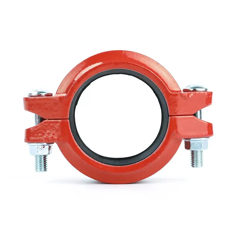
1-1/4″ rigid couplings typically hold certifications or approvals from recognized organizations that validate their compliance with industry standards and regulations.
Some common certifications or approvals for 1-1/4″ rigid couplings may include:
American National Standards Institute (ANSI):
ANSI/UL 213: Standard for Flexible Metal Conduit
ANSI/UL 514B: Standard for Conduit, Tubing, and Cable Fittings
Underwriters Laboratories (UL):
UL Listed: Indicates that the rigid coupling has been tested and certified by UL to meet specific safety and performance standards.
Canadian Standards Association (CSA):
CSA Certified: Indicates that the rigid coupling complies with relevant Canadian standards and regulations.
National Sanitation Foundation (NSF):
NSF/ANSI 61: Standard for Drinking Water System Components – Health Effects
FM Approvals (Factory Mutual):
FM Approved: Indicates that the rigid coupling has been tested and approved by FM to meet specific performance and quality standards.
American Water Works Association (AWWA):
AWWA C606: Standard for Grooved and Shouldered Joints
European Conformity (CE):
CE Mark: Indicates that the rigid coupling complies with European Union directives and regulations for health, safety, and environmental protection.
ISO Certification:
ISO 9001: Quality Management System Certification
These certifications or approvals demonstrate that the 1-1/4″ rigid couplings have undergone testing and evaluation by independent organizations to ensure compliance with relevant standards, specifications, and performance criteria. They provide assurance to customers, contractors, and regulatory authorities that the rigid couplings meet quality, safety, and reliability requirements for use in various applications, including plumbing, HVAC, fire protection, and industrial piping systems.
It’s essential to verify the specific certifications or approvals held by a particular brand or model of 1-1/4″ rigid coupling to ensure compliance with applicable standards and regulations in your region or industry. Additionally, adherence to local building codes and regulations may also be required for the installation and use of rigid couplings in specific applications or environments.
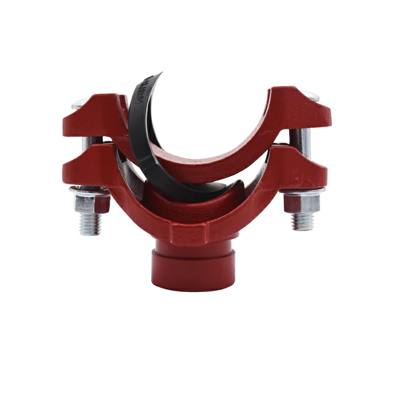
The cost of Victaulic mechanical tees compared to traditional piping connection methods depends on various factors, including material costs, labor expenses, installation time, and long-term maintenance considerations.
Here’s how Victaulic mechanical tees may compare to traditional piping connection methods in terms of cost:
Material Costs: Victaulic mechanical tees may have a higher initial material cost compared to traditional threaded or welded connections. However, the difference in material costs may be offset by savings in labor and installation time.
Labor Expenses: Victaulic mechanical tees typically require less labor to install compared to traditional methods such as welding or threading. The ease of installation and reduced dependency on skilled labor can result in lower labor expenses and faster project completion times.
Installation Time: Victaulic mechanical tees can be installed more quickly than traditional piping connection methods due to their simple and straightforward installation process. This can lead to cost savings by reducing labor hours and minimizing project downtime.
Specialized Equipment: Traditional piping connection methods may require specialized welding equipment, threading machines, victaulic mech tee or skilled welders, which can add to project costs. Victaulic mechanical tees often require standard hand tools and do not necessitate specialized equipment or highly skilled labor, resulting in potential cost savings.
Maintenance Costs: Victaulic mechanical tees are designed for ease of maintenance and repair, allowing for quick and straightforward disassembly and reassembly when needed. Traditional piping connection methods may require more extensive maintenance procedures, leading to higher long-term maintenance costs.
System Flexibility: Victaulic mechanical tees offer greater flexibility in system design and layout changes compared to traditional methods. This flexibility can result in cost savings by reducing the need for costly modifications or retrofitting of existing piping systems.
Long-Term Performance: Victaulic mechanical tees are engineered for durability and reliability, with proven performance in various applications and environments. While they may have a higher upfront cost, their long-term performance and reliability can result in cost savings over the life of the piping system compared to traditional methods that may require more frequent repairs or replacements.
Overall, while Victaulic mechanical tees may have a slightly higher initial cost compared to traditional piping connection methods, the potential savings in labor, installation time, maintenance, and long-term performance can make them a cost-effective solution for many piping applications. It’s essential to consider the specific requirements and constraints of each project when evaluating the overall cost-effectiveness of Victaulic mechanical tees compared to traditional methods.
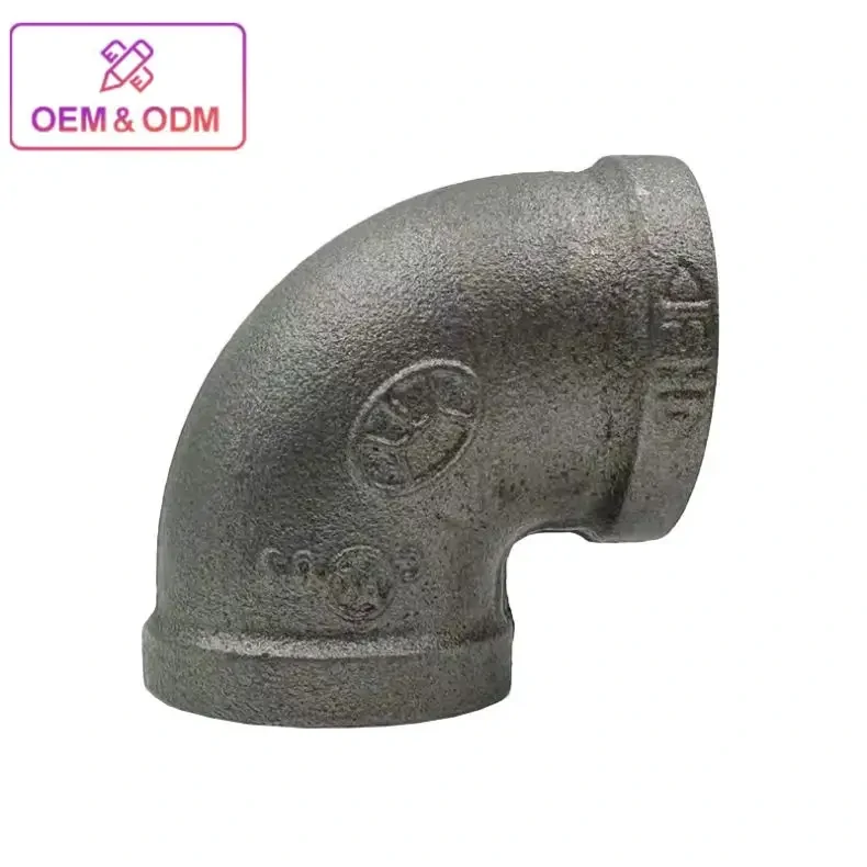
While black malleable iron pipe fittings offer various advantages, they also have limitations and drawbacks that should be considered when selecting materials for a piping system.
Some of these limitations include:
Corrosion Susceptibility: Despite being more corrosion-resistant than standard cast iron fittings, black malleable iron fittings are still susceptible to rust and corrosion over time, especially in environments with high humidity, moisture, or exposure to corrosive substances. This limitation may necessitate regular inspection, maintenance, and protective measures to prevent degradation and ensure the longevity of the fittings.
Brittleness: Malleable iron fittings are less ductile than other materials such as steel or brass, making them more prone to cracking or fracturing under certain conditions, particularly in applications where they are subjected to impact or stress. This brittleness can pose a risk of failure, especially in high-pressure or high-stress environments.
Limited Temperature Range: Black malleable iron fittings have a limited temperature range compared to materials like stainless steel or copper. They may not be suitable for applications involving extremely high or low temperatures, as they can become brittle at low temperatures and lose strength at high temperatures, potentially compromising their performance and integrity.
Threaded Connections: Black malleable iron fittings typically rely on threaded connections, which can be more prone to leaks compared to welded or soldered connections, especially if not properly sealed or installed. black malleable iron pipe fittings Threaded connections may also require periodic re-tightening or resealing to maintain a leak-free seal over time.
Weight: Malleable iron fittings tend to be heavier than fittings made from other materials such as PVC or plastic, which can make handling and installation more labor-intensive, especially in large or complex piping systems. The additional weight may also increase shipping costs and require additional support structures.
Cost: While black malleable iron fittings are generally more affordable than materials like stainless steel or brass, they may still be more expensive than alternative materials such as PVC or galvanized steel. The initial cost of malleable iron fittings, along with potential maintenance and replacement expenses, should be considered when evaluating overall project costs.
Environmental Impact: Malleable iron production processes can have environmental impacts, including energy consumption, emissions, and waste generation. While efforts are made to minimize these impacts through sustainable practices and recycling initiatives, the environmental footprint of malleable iron fittings should be considered when assessing their suitability for a project.
Despite these limitations, black malleable iron fittings remain a popular choice for various piping applications due to their durability, strength, and compatibility with a wide range of pipe materials. However, it’s essential to carefully evaluate the specific requirements and conditions of a project to determine whether malleable iron fittings are the most suitable option. Alternative materials and fittings may offer better performance, longevity, or cost-effectiveness depending on the application.
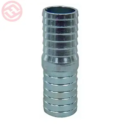
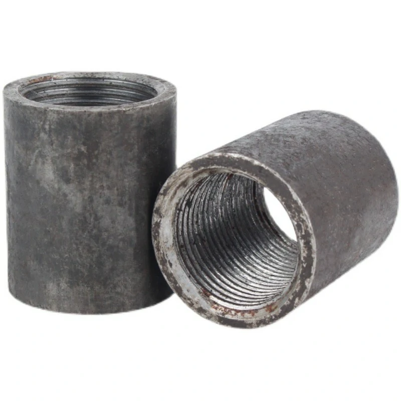
Threaded pipe nipples play a crucial role in ensuring proper flow and distribution within a piping system by facilitating connections between pipes, fittings, and other components.
The dimensions of threaded pipe nipples are carefully designed to achieve several key objectives that contribute to efficient flow and distribution:
Length: The length of threaded pipe nipples determines the distance between connected components, such as pipes, fittings, or valves. Proper length ensures that there is sufficient space for the connection to be made securely without excessive strain or stress on the threads. It also allows for proper engagement of the threads to create a tight and leak-free seal.
Diameter: The diameter of threaded pipe nipples corresponds to the inside diameter of the pipe and determines the flow capacity of the piping system. threaded pipe nipple dimensions Proper diameter selection ensures that the nipple matches the pipe size, allowing for smooth and unrestricted flow of fluids through the system. It also helps maintain consistent flow rates and pressure levels across the piping network.
Thread Pitch and Profile: The thread pitch and profile of threaded pipe nipples are standardized to ensure compatibility with corresponding fittings and components. Proper thread pitch and profile allow for secure engagement between threads, preventing leaks and ensuring a reliable connection. Standardization also facilitates interchangeability and ease of installation across different piping systems.
End Configuration: Threaded pipe nipples may have different end configurations, such as tapered or straight ends, depending on the application and connection requirements. Tapered ends are commonly used for NPT (National Pipe Taper) threads, where the diameter decreases towards the end to create a tight seal when fully engaged. Straight ends are typically used for BSPT (British Standard Pipe Taper) threads, which rely on an external sealant to achieve a leak-free connection.
Material and Coating: The material and coating of threaded pipe nipples are selected based on factors such as corrosion resistance, temperature, and pressure requirements. Proper material selection ensures that the nipples can withstand the operating conditions of the piping system while maintaining integrity and reliability over time.
By considering these factors and adhering to industry standards and specifications, threaded pipe nipples help ensure proper flow and distribution within a piping system. Properly sized and installed nipples facilitate efficient fluid transfer, minimize pressure losses, and maintain system performance and reliability. Regular inspection and maintenance of threaded connections are also essential to prevent leaks, ensure safety, and optimize the overall efficiency of the piping system.
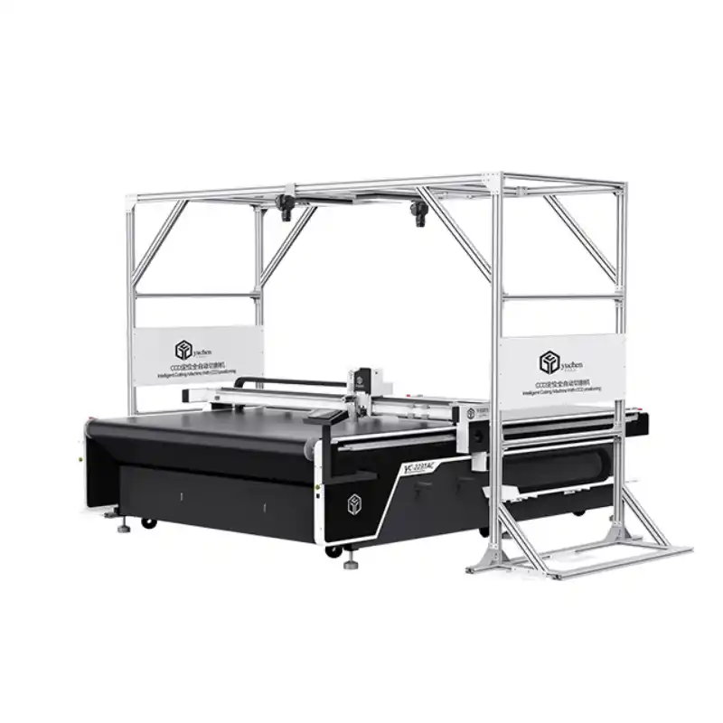
The handling of fabric stretching or distortion during cutting is a crucial aspect of T-shirt cutting machines to ensure accurate and precise cutting results.
Here’s how T-shirt cutting machines typically handle fabric stretching or distortion:
Advanced Fabric Control Systems: Many modern T-shirt cutting machines are equipped with advanced fabric control systems that minimize stretching or distortion during cutting. These systems may include features such as tension control mechanisms, adjustable feeding speeds, and precise fabric handling mechanisms to maintain fabric integrity throughout the cutting process.
Gripper Systems: T-shirt cutting machines often use gripper systems or vacuum beds to securely hold the fabric in place during cutting. These systems prevent excessive movement or shifting of the fabric, reducing the risk of stretching or distortion. Gripper systems can be adjustable to accommodate different fabric types and thicknesses while maintaining a firm grip.
Optimized Cutting Paths: T-shirt cutting machines employ optimized cutting paths and patterns to minimize fabric movement and distortion. By strategically planning the cutting path, the machine can minimize the amount of fabric manipulation required, reducing the risk of stretching or distortion along the cut edges.
Precise Cutting Mechanisms: The cutting mechanisms of T-shirt cutting machines are designed to deliver precise and clean cuts without causing excessive tension or deformation to the fabric. Various cutting methods, such as rotary blades, laser cutting, or ultrasonic cutting, may be used depending on the machine’s capabilities and the fabric type. These cutting mechanisms are carefully calibrated to ensure minimal fabric distortion during the cutting process.
Real-Time Monitoring and Adjustment: Some T-shirt cutting machines feature real-time monitoring and adjustment capabilities to detect and compensate for fabric stretching or distortion during cutting. Sensors and feedback systems may be integrated into the machine to monitor fabric tension, alignment, and movement, allowing the machine to make necessary adjustments to maintain cutting accuracy.
Pre-Treatment or Stabilization: In some cases, pre-treatment or stabilization techniques may be employed to minimize fabric stretching or distortion before cutting. This may involve processes such as pre-shrinking the fabric, applying stabilizing agents, or using tensioning devices to condition the fabric for cutting.
Operator Training and Skill: Proper operator training and skill play a significant role in minimizing fabric stretching or distortion during cutting. Operators need to understand the machine’s capabilities, fabric characteristics, and cutting techniques to optimize cutting performance and minimize fabric handling errors that could lead to stretching or distortion.
By incorporating these techniques and features, T-shirt cutting machines can effectively handle fabric stretching or distortion during cutting, ensuring accurate and high-quality results for T-shirt production.
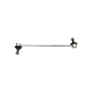
Stabilizer links (also referred to as sway bars, anti-sway bars, or anti-roll bars) are components of a vehicle’s suspension system designed to reduce body roll and improve handling. By connecting the left and right sides of the suspension together, front stabilizer links help to prevent excessive lean when cornering and can provide a flat ride even on rough surfaces. Rear stabilizer links, on the other hand, keep the vehicle stable as you drive. While vehicles with a multi-link or McPherson strut suspension system are considered independent suspension for a smoother ride, they need to be linked together for better handling and control. They also improve steering response and reduce tire wear due to their ability to keep all four tires firmly on the ground.
Stabilizer links are an important part of any suspension system because they significantly improve both the comfort and performance of a vehicle, but they can wear out and break. Naturally, that leads to handling issues and noises.
In this article, we’ll discuss the common reasons why stabilizer links break, how you can identify a broken link, and ways you can help prevent them from getting damaged.
Common causes of stabilizer link breakage
Stabiliser links are a short rod that joins the end of the stabilizer bar to a mounting point on the control arm or shock absorber. For some, a ball and socket on either end allow for movement while increasing side-to-side stability by making the chassis more rigid. Others are mounted with a studs and nuts, insulated by bushings. These small links are a weaker spot in the suspension than the stabilizer bar, control arms, ball joints, and other components, and they’re likely to wear out or break before other parts.
Causes of a broken stabilizer link can include:
Wear and tear. Tens of thousands of miles of driving with the small ball and socket at either end moving constantly inevitably wears down. The socket becomes loose and there’s excessive movement, and the link can actually come apart. In some instances, the boot can crack or tear, letting sand and dirt into the joint and the grease to escape, and it causes damage quickly. Symptoms usually show up before it separates, although it can break without regular inspection and lubrication. In certain types of links, the bushings on either end can squish or crack, creating excessive play.
Road damage. Driving over rough surfaces or speed bumps, or impact with a curb or another object on the road, can stress the stabilizer link. It’s possible for the ball to separate from the socket from a hard impact or for the rod to break or a weld to fail. On banana-style links, the rubber bushings can tear or the studs can break.
Overloading. Filling a vehicle with more cargo than it’s rated to carry or towing a trailer that exceeds the vehicle’s rating places undue stress on stabilizer links. Especially when cornering, more weight transitions to the outside wheel and the stabilizer link is expected to bear an excessive weight load. Stabilizer links can separate, bend, or snap.
Corrosion. Positioned at the wheels and constantly exposed to harsh conditions and road materials, stabilizer links can rust or corrode over time. The corrosion weakens the structure’s strength, inviting damage or breakage.
Signs of a broken stabilizer link
A broken or damaged stabilizer link on your car can be a potentially dangerous situation, leading to impaired handling and increased body roll. The key to maintaining your vehicle’s safety is being aware of the signs and symptoms of a problem with the stabilizer link so that you can act quickly and seek professional help if necessary.
The first symptom you may notice when a stabilizer link has broken or been damaged is a rattle or clunk when you drive over rough, uneven surfaces or bumps. Extra play in the small ball joints on either end causes the noise as it moves. A separated link can also cause even more noise if it’s contacting other components as you drive. It’s very noticeable in vehicles with banana stabilizer links.
Another symptom is excessive body roll when turning corners or taking sharp turns. This is due to the fact that the stabilizer links are designed to help reduce body motion, so without them present you will start to feel much less stability when cornering. Additionally, there may also be an increase in noise coming from other suspension system components as the extra force applied by the unbalanced links puts additional strain on other parts of your suspension.
For links in the rear suspension, you might be able to notice a floating feeling, like the rear suspension is operating separately from the rest of the vehicle.
Another sign that you need to look out for is uneven tire wear. This can occur if the altered weight distribution caused by damaged or missing stabilizer links causes your tires to bear more weight than they should be. Uneven tire wear usually appears as cupping on your tires and should not be ignored as it can lead to further problems down the line.
If you’re noticing any of these problems with your car, then it’s important that you take action immediately and have it checked out by a qualified mechanic as soon as possible. A broken or damaged stabilizer link can lead to impaired handling issues if left untreated.
Preventing stabilizer link breakage
The first thing to keep in mind to prevent damage to stabilizer links is regular maintenance checks on the suspension. Bushings, such as stabilizer bar bushings and control arm bushings, act as cushions between metal components in your vehicle’s suspension system. When these bushings wear out due to age or stress, it can increase the strain on stabilizer links, causing play or breakage. It’s important to have bushings checked regularly for signs of wear and tear so they can be quickly replaced when needed. If stabilizer links are greasable, lubricate them during every maintenance check.
Another factor to consider is avoiding large loads being applied to the suspension. This means both passengers or cargo in your vehicle as well as anything attached externally like a trailer or roof rack. Any additional weight put on these links will cause them strain over time which can eventually lead to breakage if left unchecked. It’s best to try to avoid carrying large amounts of weight when possible and check that you stay within your Gross Vehicle Weight Rating.
Driving mindfully can prevent many of the issues you can experience with your suspension including broken stabilizer links. Reduce the risk of breakage or wear by avoiding rough roads and potholes when you’re able, and slow down over speed bumps.
Finally, proper installation of new parts is also key when preventing link breakage. If you’re replacing or repairing any part of your suspension system yourself, make sure you follow all instructions carefully and take extra care when attaching new parts. Loose or improperly installed components as well as neglecting to have a wheel alignment performed can contribute to wear on links.
Conclusion
While simple in design, stabilizer links are an incredibly important component of your suspension system that ensures dependable handling. They’re susceptible to wear and tear, and they’re a weak spot in your suspension to help avoid damage to other even more important and expensive parts. You’ll often notice signs that stabilizer links are about to fail, and they should not be overlooked. At the first sign of a problem, replace worn-out or damaged links.
Preventing issues with stabilizer links and other suspension parts can be aided by routine vehicle inspections. If you come across a broken or loose link, it’s more than just getting rid of the annoying noise it causes. It’s about health and safety by maintaining these parts.
At TRODO, you’ll have all of the parts you need for most vehicle makes and models at your fingertips. Find stabilizer links, suspension components, and much more with fast processing and delivery to your door. We’ll confirm you have the right parts for the job – our in-house experts check all ordered parts to ensure they’re compatible with your vehicle, and at no charge to you.
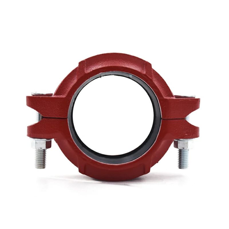
What are the advantages and disadvantages of rigid and flexible couplings?
Couplings are mechanical devices that connect two shafts and transmit torque and power between them. They are essential for many machines and applications, such as pumps, compressors, generators, conveyors, and more. However, not all couplings are the same. Depending on the design, alignment, and load conditions of the shafts, you may need to choose between rigid and flexible couplings. In this article, you will learn what are the advantages and disadvantages of each type of coupling and how to select the best one for your machine design.
1Rigid couplings
Rigid couplings are the simplest and most economical type of couplings, consisting of two flanges, hubs, or sleeves that are bolted or clamped together around the shaft ends. They provide a fixed and rigid connection between the shafts, without allowing any relative movement or misalignment, making them suitable for applications with precisely aligned shafts with steady and uniform loads. Rigid couplings have many advantages, such as being easy to install and maintain, compact and lightweight, reliable and durable, and cost-effective. However, they cannot accommodate misalignment between the shafts, absorb shock or torsional loads, or compensate for thermal expansion or contraction of the shafts; all of which can cause serious damage to the shafts and coupled equipment.
Rigid Coupling Advantages : 1. High Torque Transmission 2. Accurate shaft alignment. 3. Simple Design 4. Low Maintenance Disadvantages: 1. No Misalignment Compensation 2. Limited Damping 3. Less Tolerance for Shaft Deflection
2Flexible couplings
Flexible couplings are designed to accommodate some degree of misalignment between the shafts and provide a smooth transmission of torque and power while absorbing shock, vibration, and noise. They are suitable for applications with moderate misalignment and variable load conditions. The advantages of flexible couplings include the ability to reduce stress, vibration, noise, and wear on the shafts and bearings; absorb shock, impact, or torsional loads; and compensate for thermal expansion or contraction. However, they are more complex and expensive than rigid couplings, larger and heavier due to the flexible element, less reliable and durable due to repeated flexing, and require more maintenance and inspection.
We have used Lovejoy Jaw Coupling to connect Worm Gearbox output shaft machine drive. There will be slight degree of misalignment. Flexible couplings can accommodate angular misalignments between shafts, ensuring smooth and efficient power transmission without inducing excessive stress on connected components
3How to choose the right coupling
The right coupling for your machine design depends on several factors, such as the type and size of the shafts and coupled equipment, the alignment accuracy and tolerance of the shafts, the load characteristics and variations of the application, the environmental conditions and operating temperature of the machine, and the cost and availability of the coupling. Generally, rigid couplings are suited for applications with well-aligned shafts and steady, uniform loads, while flexible couplings are best for moderately misaligned shafts and variable, dynamic loads. However, it is important to consider the specific requirements and constraints of your machine design when selecting a coupling to ensure that it meets your needs.
4Here’s what else to consider
This is a space to share examples, stories, or insights that don’t fit into any of the previous sections. What else would you like to add?
Identifying the material composition of an aluminum rigid coupling can be done through several methods, including visual inspection, markings, and testing.
Here are some common ways to identify the material composition of an aluminum rigid coupling:
Visual inspection: Start by visually examining the coupling for any distinctive characteristics that may indicate it is made of aluminum. Look for a silver-gray color, lightweight construction, and a smooth surface finish typical of aluminum materials. However, visual inspection alone may not always be conclusive, as other materials may have similar appearances.
Manufacturer markings: Check for any markings or labels provided by the manufacturer on the coupling. Manufacturers often label their products with information such as material composition, specifications, and product codes. Look for markings that indicate the coupling is made of aluminum, such as “Al” or “AL” for aluminum.
Product specifications: Review the product specifications provided by the manufacturer or supplier. This information may include details about the material composition of the coupling, such as the type of aluminum alloy used (e.g., 6061-T6, 6063-T6) and any applicable industry standards or specifications.
Material testing: If visual inspection and markings are inconclusive, you can perform material testing to determine the composition of the coupling. aluminum rigid coupling Common methods for testing aluminum materials include spark testing, density measurement, and spectroscopy analysis. These methods can provide more accurate and reliable results but may require specialized equipment and expertise.
Consultation with supplier or manufacturer: If you’re unsure about the material composition of the coupling, you can contact the supplier or manufacturer for clarification. They can provide detailed information about the materials used in the production of the coupling and any relevant specifications or certifications.
By using a combination of these methods, you can accurately identify the material composition of an aluminum rigid coupling and ensure that it meets the requirements of your application. It’s important to confirm the material composition before installation to ensure compatibility with the piping system and to prevent issues such as corrosion or structural failure.